Here's the end result:
Here's how it works:
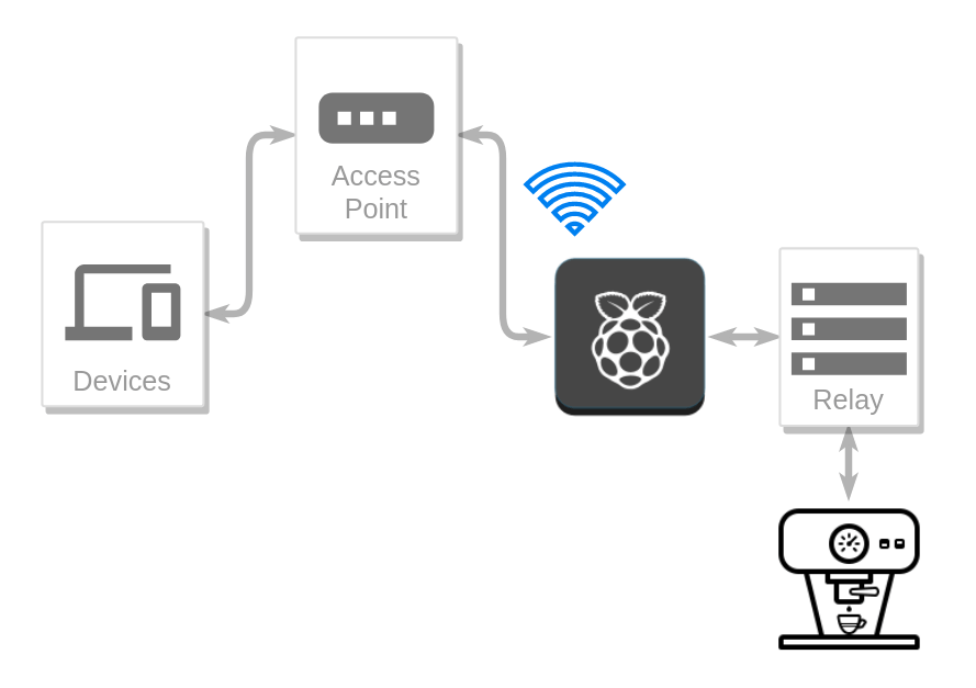
Table of contents
- Hardware used / What you need
- Decide on functionality
- Identify which connections need soldering
- Figure out how a relay board works
- Figure out how to control the relay board
- Decide where to put the Raspberry Pi
- Begin soldering
- Setup needed software
- Connecting coffee machine to relay
- Closing words
- Comments
Hardware used / What you need
- Raspberry Pi Zero W
- I personally used a Raspberry Pi Zero with a Wi-Fi USB dongle. I'd recommend the Raspberry Pi Zero W though.
- Wires
- Relay Board/s
- Soldering iron
- Optional:
- Mechanical Switch
- Power Socket
- Drill
Step 1:
Decide on functionality
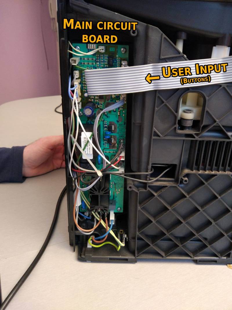
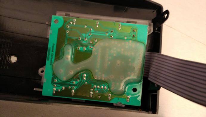
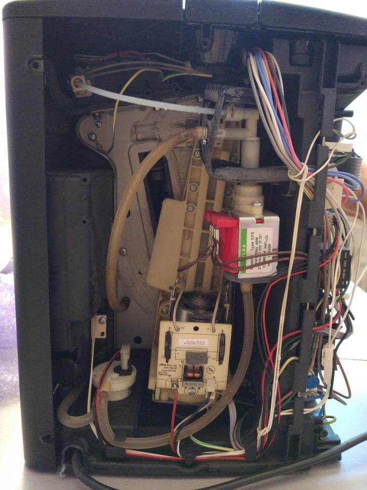
For starters, unscrew your machine and find out how the buttons interact with the main circuit board.
Here you can see that the buttons in the front, feed the main circuit board with information via these connections
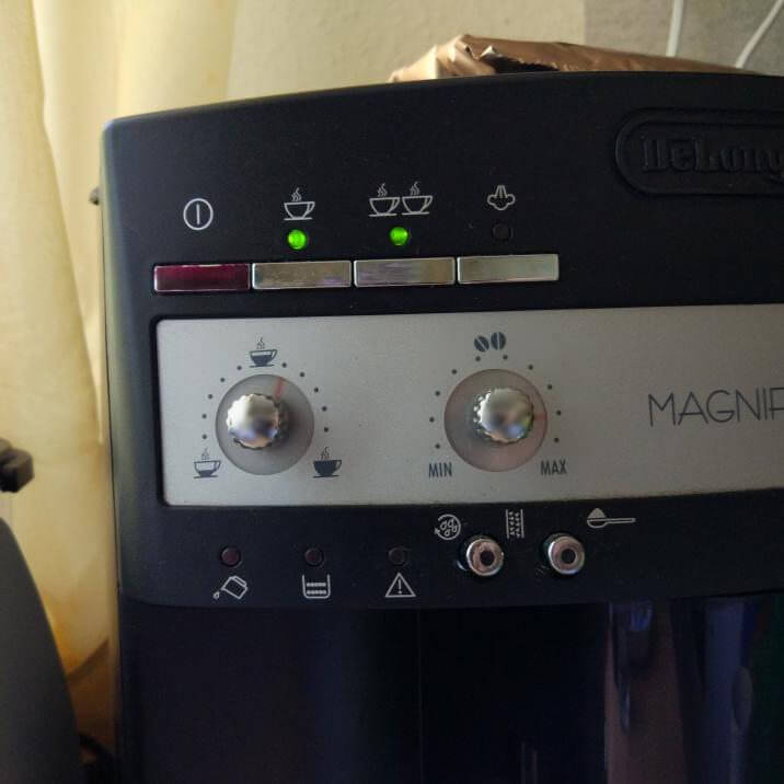
Behold the front i.e. the user interface
The whole theory for this project is that we're going to programmatically press buttons.
With hardware, you have a physical button, which looks like this
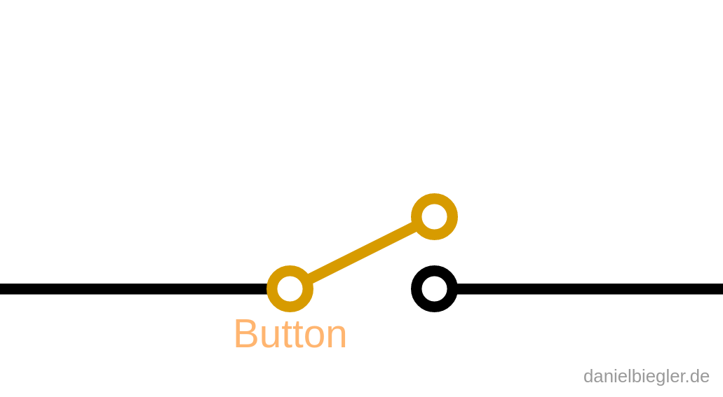
When you press the button down, you close the circuit which enables the charge to move.
This is cool, because simply adding another "button" is all we need, see here
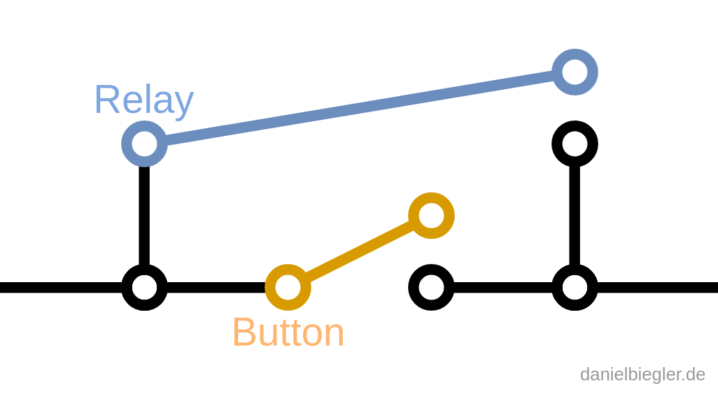
This way it doesn't matter which button you're pressing, be it the physical button on the machine or our future digital "button"; Both buttons may complete the circuit!
This second "button" will be our relay board.
For this project, I decided that I'm only interested in controlling the following three buttons:
- On/Off
- Brew one cup
- Brew two cups
Decide for yourself what kind of functionality you're interested in.
Step 2:
Identify which connections need soldering
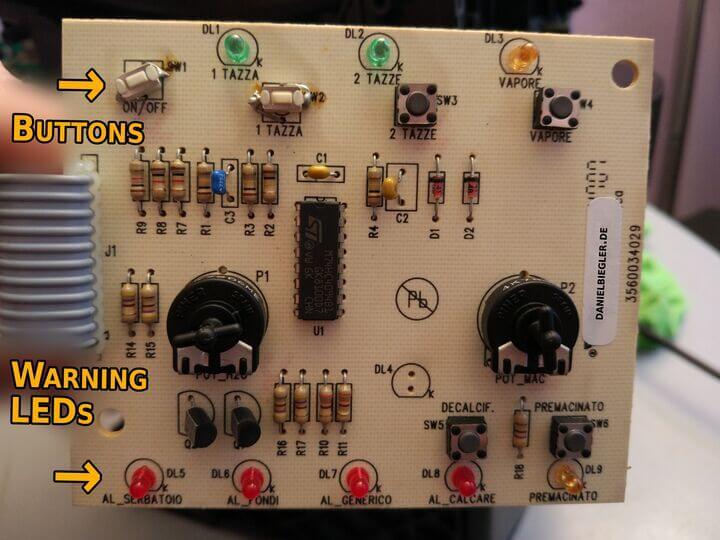
I decided that this is a step I should take early on to rule out possible problems with the board. The connections might be obstructed by hot glue for example.
Turn the user interface board around and identify the specific lanes.
Some tracing later and I identified all the info I need. One wire to each colored line plus one for ground (GND).
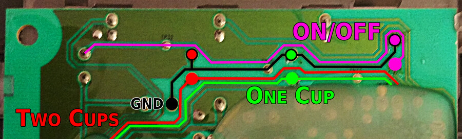
Notice how the three buttons are connected to the same GND, the black line. This means we only need a single wire for the GND instead of wiring up each button individually, cool!
Step 3:
Figure out how a relay board works
A relay is basically just an electrically operated switch.
Let charge move through a control pin and the switch flips. Here's a short video, made by Simon A. Eugster
If we connect such a relay to a button on our coffee machine, we can electrically control it!
Step 4:
Figure out how to control the relay board
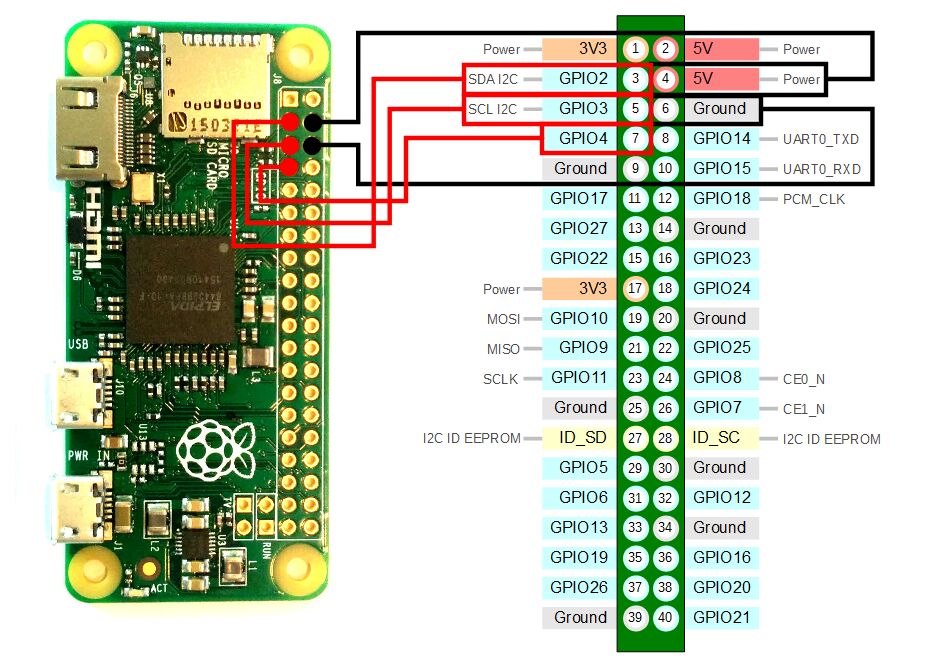
The Raspberry Pi has these so called general purpose input/output pins. (short: GPIO pins)
They look like this:
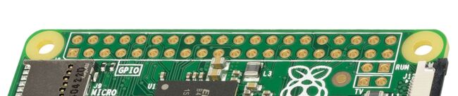
We're going to use the output pins on our Pi to electrically control the relay, which then will control the coffee machine. Remember the diagram in the beginning, here:
How do we interact with a GPIO pin?
The Raspberry Pi is running Linux which means "Everything Is A File"; In other words, you can control the GPIO pins simply by writing to a file. Don't worry, I published my code and will walk you through it. More on the specifics later.
How do we tell the Pi when to flip the pin (relay)?
I came up with a simple REST API which means that the Pi will be waiting for a specific network request and act accordingly, either doing what it's told or reporting back an error.
Three buttons want to be controlled, so the Pi will be listening for these three instructions:
| Command | Action |
| cups=1 | Brew 1 cup. |
| cups=2 | Brew 2 cups. |
| power=toggle | Toggle power. |
Having such an interface makes it possible to create multiple different ways of interacting with the Pi; Meaning, having a device that can send network requests (Your desktop, laptop, tablet, phone, watch, ..) enables you to interact with the coffee machine!
How do we send a network request?
I found building a little website the most intuitive approach for interaction since then also other people in my network can use this service. You could decide on something different here.
(Scripting comes to mind)
Step 5
Decide where to put the Pi
Your Pi has to reside either in or outside of the coffee machine. I opened up the back and luckily found plenty of space to work with.
I do not own a case for the Pi so some sort of backplate would be nice to have. Some plastic from the basement will do. Drill some holes, turn some screws et voilà:
Sticking it onto the back wall seemed reasonable enough:

Step 6:
Begin soldering
Relay boards generally need a pin for power (VCC), another pin for ground (GND) and one pin for each channel. I want to control three buttons so I need five pins in total. I marked them here:
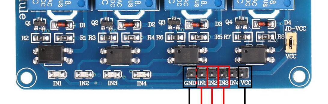
Here are the pins that I used
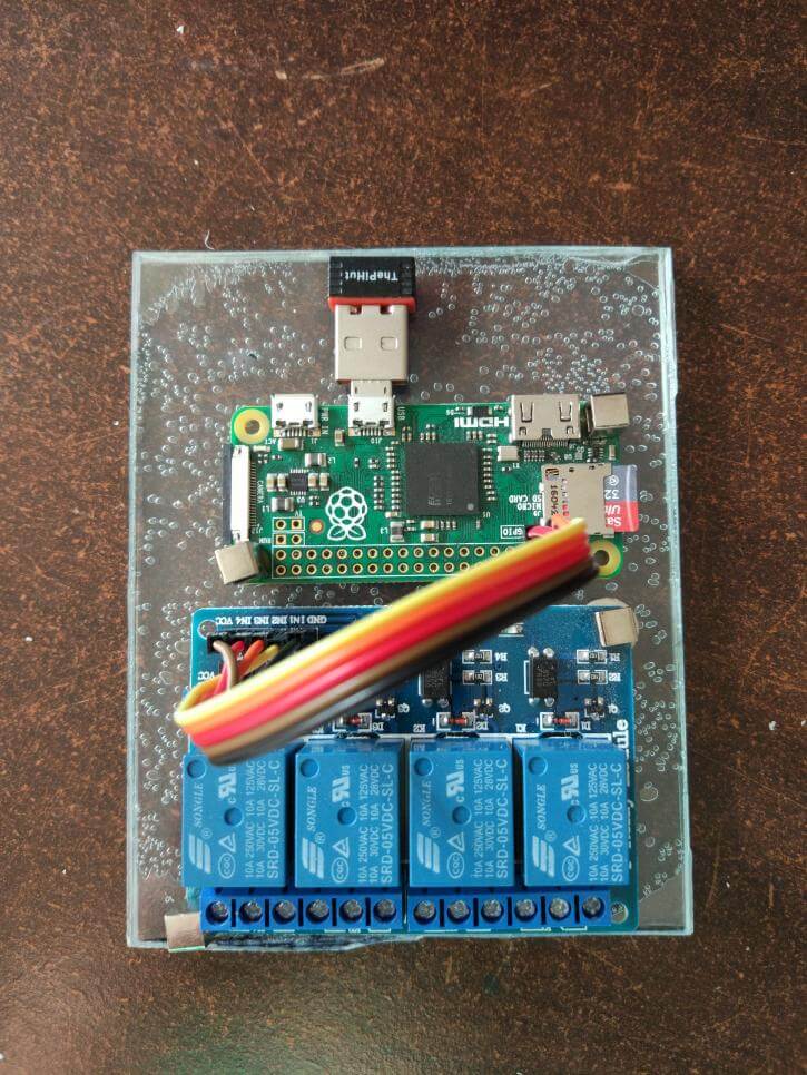
After soldering and powering up your Pi, it should look similar to this:
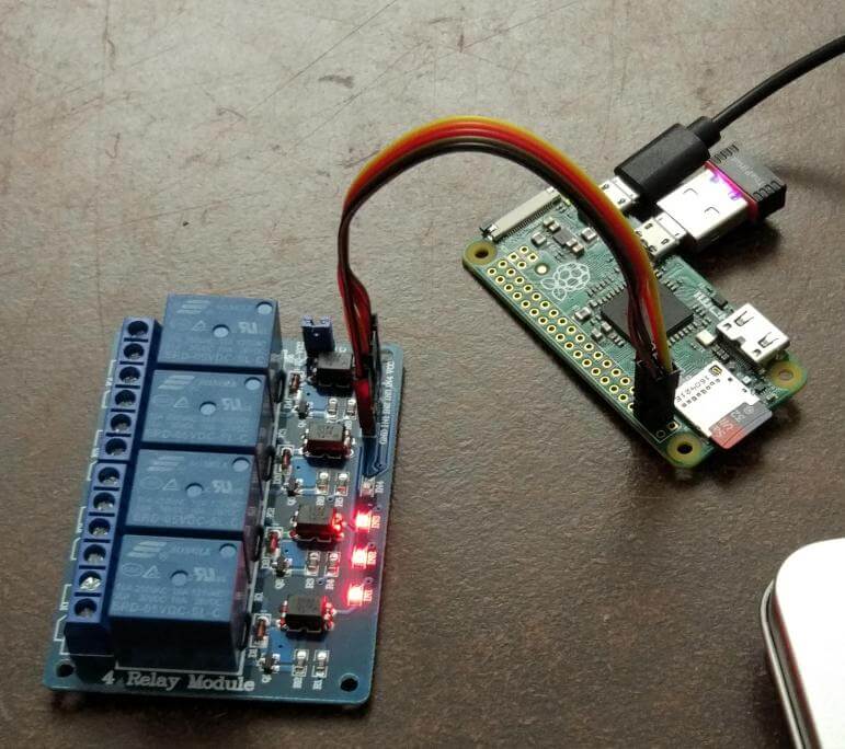
Notice the three shining LEDs, they're indicating the state of the relays. They are ON by default and have to be turned OFF after booting your Pi. This task will be automated via a startup script; More on that later.
Sidenote:
At this point in the project everything was new to me, so I tried toggling the relays manually. For this tutorial I'll be getting into the technical stuff later on. If you're familiar with Bash and already want to play around with it, consult my initialization script.
The Pi's done, on to the coffee machine.
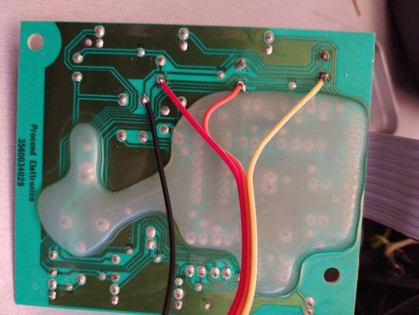
Remember the traced board:
After soldering it should look similar to this:
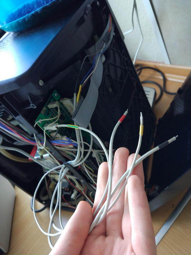
Cool, progress! You may need to extend your wires depending on how big your coffee machine is. Mine reach from the front to the back like so:
Depending on how you want to provide power to your Pi you might be done soldering now!
My father suggested that you could use the same power that drives the coffee machine to also power the Pi. This way no external cable would be visible, which is pretty neat if you ask me!
WARNING: I'd suggest only doing this if you truly know what you're doing! Working with such high voltages is dangerous. Only attempt this if you know what you're doing.
We put a small power socket inside the coffee machine which holds a run of the mill AC to DC USB Adapter. This adapter then powers the Pi via USB. See here:
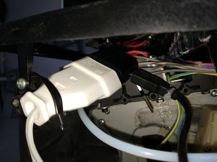
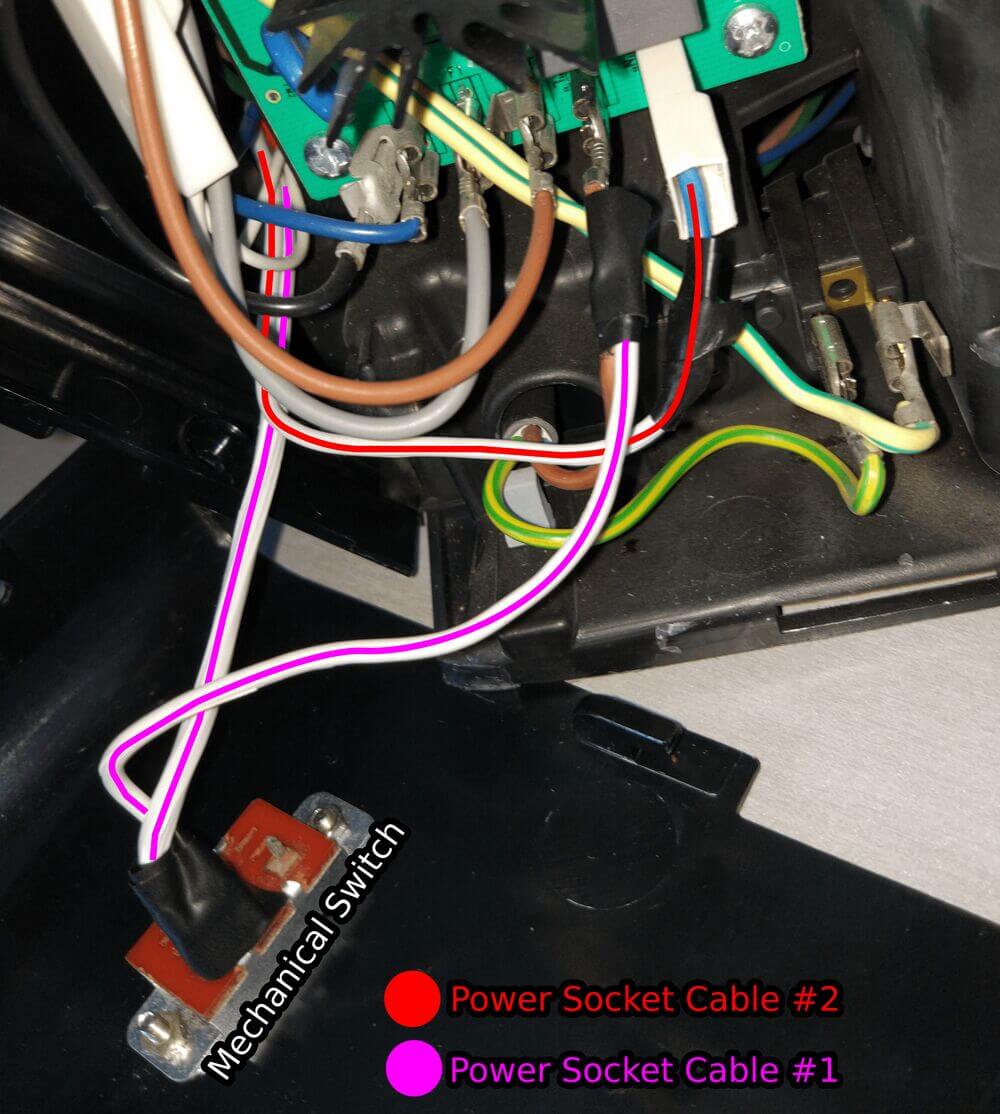
To be able to turn the Pi ON or OFF a little mechanical switch was used. The white socket has two cables going out from it. One of it needs to go into the mechanical switch and the other one into the coffee machine.
Identify where the machine draws power from by looking for a PROBABLY brown, blue and a yellow+green cable. (Check the colours for your region, these colours are only true for Europe!)
Connect the power socket cables to the brown and blue cable like in the following image. It doesn't matter which specific cable of the power socket goes into the blue or brown one.
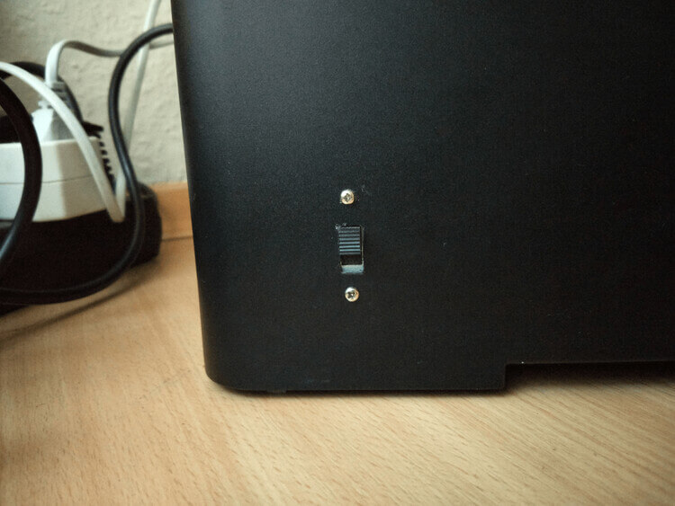
Cut a hole for the switch and enjoy the hidden goodness.
Step 7
Setup needed software
Note:
All my code for this project can be found here.
I coded the aforementioned REST API in some basic PHP, because a webserver with PHP support was already installed on my Pi.
As webserver (+ PHP) one has a couple of options to choose from, there are neat little articles from the Raspberry Pi Foundation itself. It really doesn't matter which one you'll choose, just pick one. For example you could go for NGINX or Apache. The process is pretty much the same and a "set-it-and-forget-it"-step.
Download and install, enable some stuff, done.
How exactly do we control the GPIO pins
The pins are represented as files on your Pi. You can find them in the /sys/class/gpio folder, see here:
$ ls /sys/class/gpio
export  gpiochip0  unexport
This folder is pretty interesting, in that there are two special files, export and unexport.
The export file sets up and enables the files of a specific pin.
The unexport file removes the created files.
A little example will help make clear how this works: You simply write the number of the GPIO pin into the export file, then you get access to the needed files. The only caveat is that by default you need root privileges because this is a system directory. For example I want to activate the 5th GPIO pin so I write the number 5 into export:
$ echo 5 > export
$ ls /sys/class/gpio
export  gpio5  gpiochip0  unexport
See how now there's an additional folder called gpio5! You can go inside and list its content via:
$ cd /sys/class/gpio/gpio5
$ ls
active_low  device  direction  edge  power  subsystem  uevent  value
Here are more special files that let you configure this pin. For us direction and value are interesting because with those two we could start controling our relay! Inspect the contents of the files via:
$ cat direction value
in
1
The current direction of this pin points in and its value is 1. Imagine hooking up an external device to this pin, this way you could establish communication between different systems by monitoring the value. Cool, right?
Our goal is to output charge to the relay, so we have to change to direction from in to out.
Simply write out to the direction file like so:
$ echo out > direction
$ cat direction value
out
0
See now the pin points outwards and has a value of 0. Super simple stuff. I was quite delighted when I tried this out for the first time because I had assumed that controlling hardware would be very finicky. All that's needed is simply writing either 1 or 0 to the value file. Who knew?
A little sidenote:
A distinction has to be made here, the export and unexport files expect not the literal pin number, but the GPIO pin number which is different. Let's stick to the example of GPIO pin number 5. On the following graphic you can see that the GPIO5 has the literal pin number of 29.
So yeah, keep that in mind.
Setup the GPIO pins we need
Like you've seen in the previous graphic I intend to use the GPIO pins 2, 3 and 4.
I wrote a script that does the steps of exporting, setting the direction, setting the value and permissions:
# Enable the needed pins.
echo 2 > '/sys/class/gpio/export';
echo 3 > '/sys/class/gpio/export';
echo 4 > '/sys/class/gpio/export';

# Change directions to "out".
echo 'out' > '/sys/class/gpio/gpio2/direction';
echo 'out' > '/sys/class/gpio/gpio3/direction';
echo 'out' > '/sys/class/gpio/gpio4/direction';

# Turn the pins off.
echo 1 > '/sys/class/gpio/gpio2/value';
echo 1 > '/sys/class/gpio/gpio3/value';
echo 1 > '/sys/class/gpio/gpio4/value';

# Change permissions so the webserver can write to the 'value'-files
chmod 777 '/sys/class/gpio/gpio2/value';
chmod 777 '/sys/class/gpio/gpio3/value';
chmod 777 '/sys/class/gpio/gpio4/value';
A reboot of the Pi resets the pins we previously exported so we need a startup service that re-enables them after booting up. I wrote this service which will run the initialization-script:
[Unit]
Description=Sets up the necessary files and permissions for the 2nd, 3rd, 4th GPIO pins to work.

[Service]
Type=oneshot
ExecStart=/bin/gpio_coffee_init.sh

[Install]
WantedBy=multi-user.target
Please notice how the service looks for the initialization script in the /bin folder /bin/gpio_coffee_init.sh. So prior to enabling this service you should move the gpio_coffee_init.sh into /bin via:
$ mv gpio_coffee_init.sh /binThen I also moved the service into /etc/systemd/system the same way via:
$ mv gpio_coffee_init.service /etc/systemd/systemAfter doing that you can try out if it works by starting the service via:
$ systemctl start gpio_coffee_init.serviceThis should set your GPIO pins up which you can check manually in the /sys/class/gpio directory, like so:
$ ls /sys/class/gpio
export  gpio2  gpio3  gpio4  gpiochip0  unexport
See, how the second, third and fourth pin got exported. Yay. If that's successful you can enable the service which means that it'll run on each startup of the Pi.
$ systemctl enable gpio_coffee_init.serviceA quick recap
- We have an initialization script which properly sets our pins up: Export them, setup direction, value and file permissions.
- This initialization script gets automatically run after booting up the Pi.
I did this once and after months of use I had never the need to change anything here. It just works.™
Deploy the website
Alright, we got the hardware stuff out of the way. Time to deploy the website.
The website files will probably reside for you in /var/www/html. This folder depends on your Linux distro though, mine are for example in /srv/http. It doesn't really matter, just find out where your server looks for files via your search engine of choice.
You can find the code of my site here. Download it and move the index.php and the vendor folder to the directory where your webserver looks for pages. The index.php file contains the actual website and the vendor folder contains the 'graphics' so to speak. If you forget to also move the vendor folder, the site will look bare bones and broken is all I'm trying to say.
Sidenote:
I don't think it's necessary here to go through all of the sites code, is it? Shoot me a comment if you think otherwise.
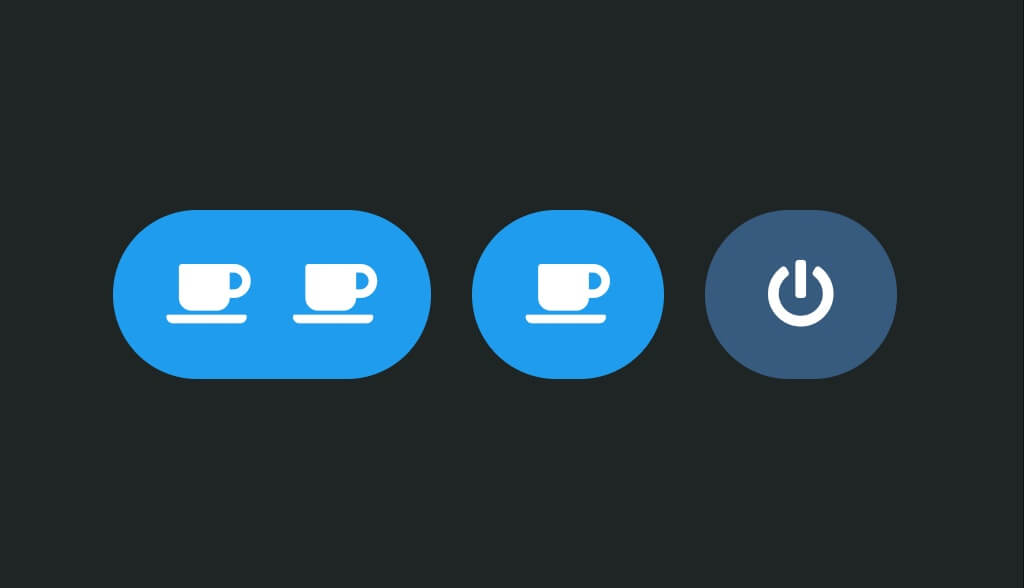
I designed the site to be minimalistic and optimized for mobile displays. It should look like this when you open it in your browser:
Last but not least two little tricks to improve the quality of life when using this service:
You could change the device name of your Pi to something like 'coffee' so that you can access it more easily inside your home network. For example my FRITZ!Box Router allows me to connect to devices inside my network via URLs like: <devicename>.fritz.box which in this case would make connecting really comfortable via coffee.fritz.box
In order to do this you simply write the name you want into the hostname file at /etc/hostname like so:
$ echo 'coffee' > /etc/hostnameAnother cool little tip is that you could add this site to your homescreen. This way you can access your coffee with one simple tap on the icon. Chrome, Firefox and Safari all support this feature, find it in the settings while visiting a site.
The website in action
Assuming the software works like expected: Finally the magical moment of putting it all together is around the corner.
Step 8
Connecting coffee machine to relay
Connecting the relay to the coffee machine is easily done, here's a a little diagram I made:
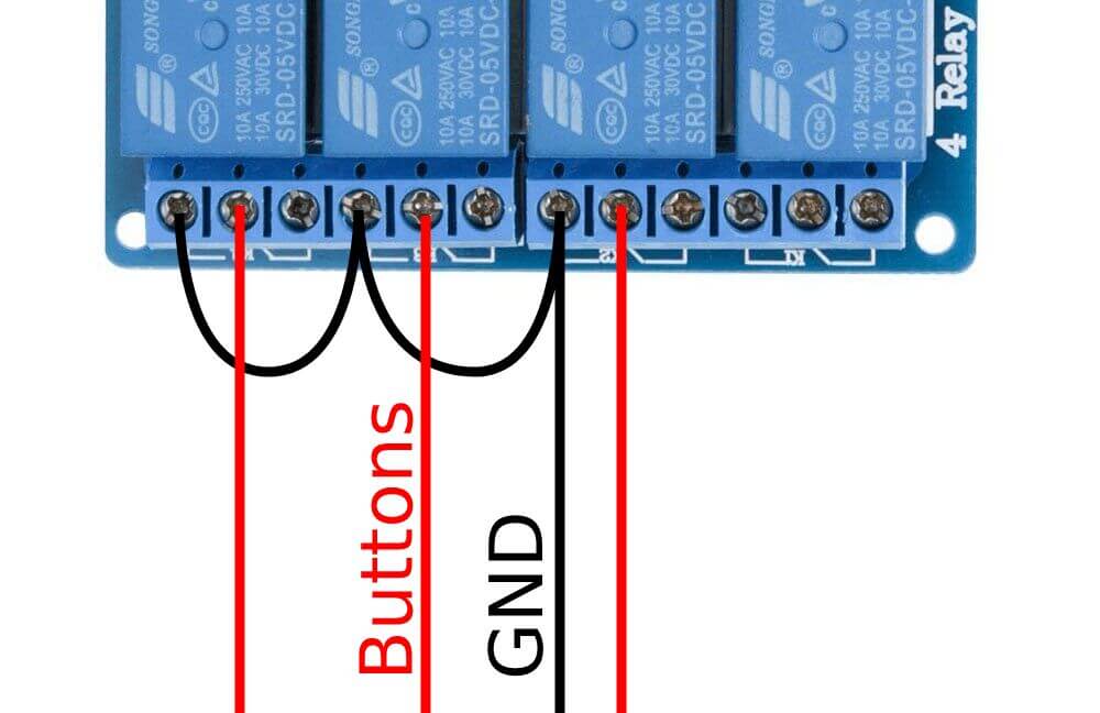
In reality it looks something like this:
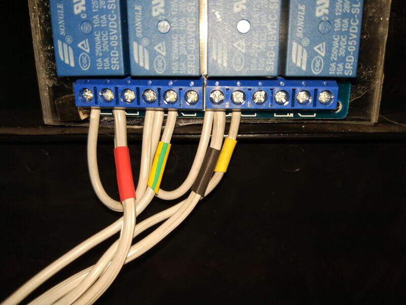
You should be done now.
Now your next coffee is only a click away!
For completeness' sake, take another look at the abstract diagram
and feel the pure bliss of operating a heavy machine with your fingertips:
Closing words
Thank you for reading through this mess. It's been my first hardware project and needed a lot of tinkering, trial and error. Looking back it seemed really daunting, but I enjoyed the road.
If you enjoyed this post, subscribing to my mailing list might be of interest to you. How about reading more about visualizing DNA and more.
I can't really give a clear answer there because it varies. You might run into danger of frying your devices if you hook something up wrong. So, please be careful. In general I'd recommend using a relay and to give it its own power source so that you can separate the circuits and protect your devices. More info here: https://en.wikipedia.org/wiki/Galvanic_isolation
If you manage to find more out, feel free to let me know! Thank you for your comment!
Do you want to change the display contents of the grinder itself? That's probably gonna be very complicated since you'd need to modify the firmware of the internal board. Maybe you can find the firmware on the manufacturers site. But then you probably need to decrypt it somehow. That's gonna be a lot of work, I don't think I can be of much help there.
Was denkst du?